

For those who missed the original post or didn't have a chance to read it, start here.
Hello again everyone,
You might remember me as the guy who was so bored and sleep deprived that decided to answer the question "could I simulate an hour of bouncing DVD logo, trace the trajectories and count the amount of perfect_corners?"
In my last post many people noticed a certain weird behaviour in my simulation. Specifically, the trajectories were leaning towards the center and also not following a 45 degree trajectory as the bouncing DVD logo simulation would require.
The starting degree issue was actually intentional on my part. I had simulated the 45 degree angle and noticed there were no perfect_corners, therefore an hour of simulation didn't bear an interesting outcome and at that point i had also asked myself if changing the starting angle would push the logo towards a higher number of "perfect corners" match.
The second issue, trajectories showing a bias for the center, was due to the logic behind my DT simulation. The dt parameter I used tried to mimic a 60Hz screen by looking at the trajectory position in discrete timesteps, reaching what was closer to 60FPS being set at 0.0167 (though it was an approximation and not a precise measurement of 60Hz).
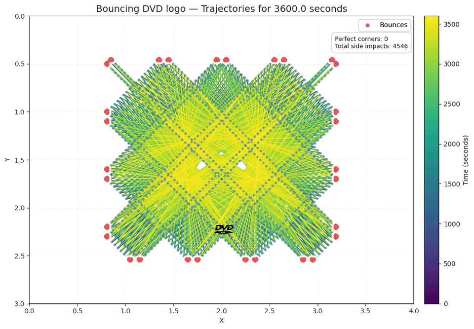
You can see in the first picture what happened when i set 45 degrees as a starting angle in my first simulation.
At this point though another, more interesting question popped in my mind. "Could I use a random search to find that angle that optimizes the perfect_corners count?"
To reply to this question though, I had to move on from a monolithic coding approach and use an object-oriented approach to develop a proper engine with an underlying set of physics rules to run over. The entire system is built this way:
– Physics core – Function with a set of physics rules for an enclosed system simulating a rectilinear motion in a space with reflective boundaries
– Three different functions with three different engines running over the established physics rules in order to test three different logics
– compute metrics function that logged the results independently
– plot function that gave out visual results.
Why three different engines though?
I told you how the initial "DT Engine" had issues and also introduced a bias. Not only that but i realized that the perfect corners count was wrong for two reasons:
– First, the DT parameter made it so that my engine "looked up" for trajectory position at given time intervals, therefore it allowed the trajectory to overshoot and then reposition it inside the system, exaggerating the perfect corners count;
– Second, The way i measured the perfect corner in the original simulation was trying to match the logo corner with the border corner, introducing a tolerance measure to log as a perfect corner even if the match was not precise;
To straighten this issue up i decided to introduce two new engines:
– An event-driven engine which just simulates the trajectory and then asks itself "where will the next collision happen?", and then brings the system there next and move on to the next collision;
– A pixel_snapping engine which uses the same event-driven engine logic and then "snaps" the trajectory to a pixel_grid that simulates the pixels of an lcd/led screen. This is a visual quantization and not a change in physics, therefore the underlying trajectory results are equal to the event-driven engine. The amount of pixels used is a hyperparameter.
At this point i redefined how i logged a perfect corner by having the sides of the logo box register a simultaneous collision event with the space borders, meaning it inevitably approached one of the corners. A collision on x and y axis simulataneously means you get a perfect_corner.
The images above are almost all extracted by this system of simulation:
Image 1 – Original simulation with a DT system on a 45 degrees angle.
Image 2 – New physics system simulation for bouncing dvd logo showing what happens when you set 45 degrees on DT Engine running on top of the physics core
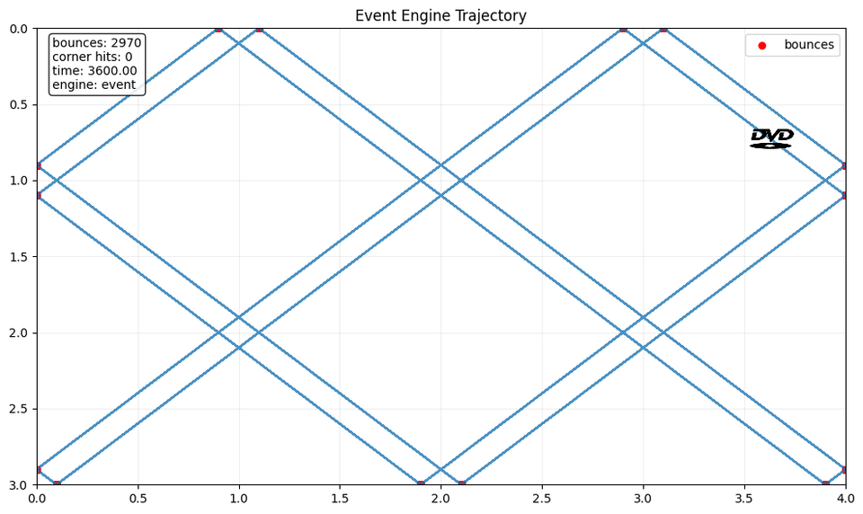
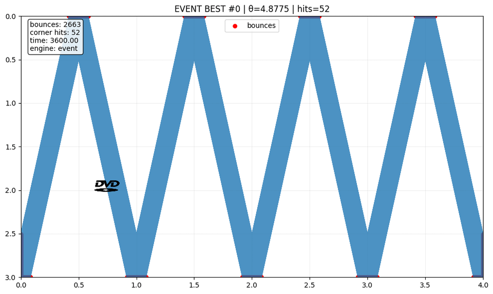
Image 3 – 45 degrees on event-driven engine
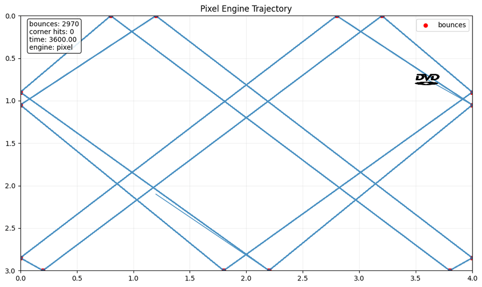
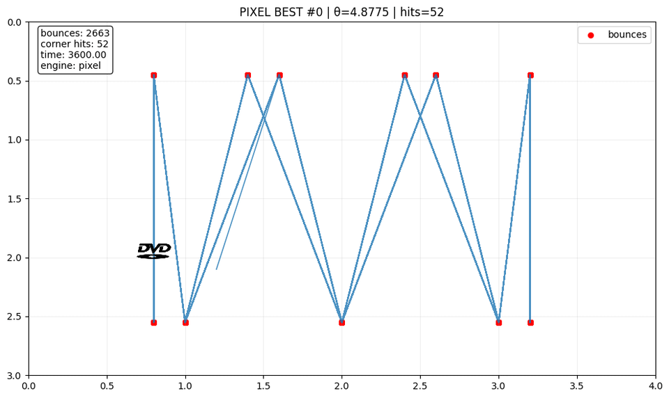
Image 4 – 45 degrees on the pixel_snapping engine
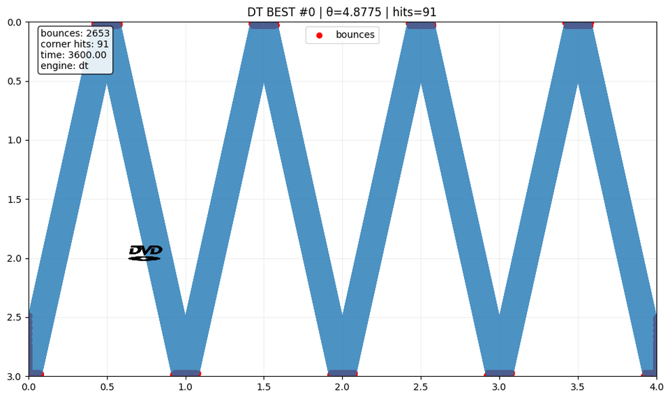
Image 5, 6, 7 – Results of Random searching a 360° degrees starting angle space to optimize the perfect_corners count. The randomly chosen corner is 279.4613° and it gets the best outcome in perfect corners.
The result i observed is that the systems are essentially quasi-periodic or non-periodic, unless you select a specific "special" set of starting angles like 45, 90 etc. and then you get a periodic trajectory which might avoid giving out perfect corners entirely.
The system i coded keeps logging the trajectories as before, and visualize them alltoghether, though i apologize for not focusing much on data visualization with the charts but all i wanted this time was to get a working plausible system.
Please NOTE: The pixel_snap visualization is smaller in the way it is represented because i wanted to avoid that the logo snapped itself to the container border creating an ambiguous visualization.
As many requested the simulation is now available on github here, commented and explained in the .ipynb notebook.
by Trollercoaster101
1 Comment
SOURCE: All data is internally generated by the simulation. The notebook was developed on Google Colab with Python. I didn’t use any external dependancy for this, just basic libraries.